What Is the Best Female Header Connector in 2026?
Choosing the best Female Header in 2026 requires more than comparing pin counts and unit prices. The connector sits quietly inside control boards, sensors, industrial equipment, and consumer electronics. Its small plastic body still carries critical electrical and mechanical responsibilities.
Market research shows why this decision deserves closer attention. Grand View Research estimated the global connectors market at approximately USD 84.8 billion in 2023. Its report also projected continued growth through 2030, driven by automation, electric vehicles, data infrastructure, and compact electronics. Mordor Intelligence likewise forecasts steady expansion, although market estimates differ by research method. That difference matters. It reminds engineers to examine real application data instead of trusting one headline figure.
Ron Bishop, founder of Bishop & Associates, has described connectors as “the essential link between electronic systems and the outside world.” His observation remains useful when evaluating a Female Header. Contact reliability, insulation material, mating cycles, pitch tolerance, plating, and solder performance can matter more than a low purchase price. A 2.54 mm header may fit a prototype perfectly, yet fail inside a vibrating enclosure. A gold-plated contact may improve durability, but unnecessary specifications can increase cost.
There is no universal winner.
The best choice depends on current, temperature, vibration, assembly method, and expected service life. This guide compares the leading Female Header options for 2026 using engineering evidence, manufacturer specifications, and practical selection experience. Some conclusions may remain imperfect, because supplier data and field conditions are not always directly comparable. That limitation should encourage careful testing, not convenient assumptions.
What Is a Female Header Connector and How Does It Work?
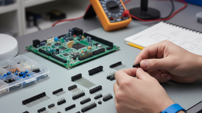
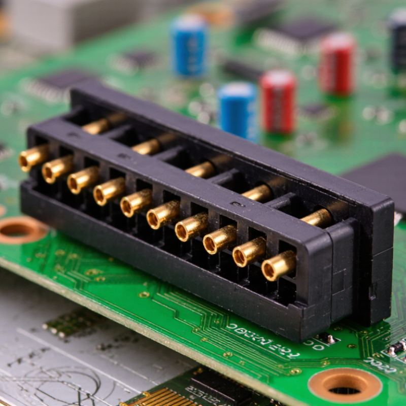
A female header connector is a small receptacle that accepts matching male pins. Its metal contacts carry electrical signals between a circuit board and another board, cable, or module. The plastic housing keeps each contact aligned and prevents accidental contact between adjacent pins.
When inserted, a male pin slides into a spring-like contact inside the socket. This pressure creates a stable electrical path. Many headers use two parallel rows, although single-row versions remain common. Through-hole headers offer strong mechanical support, while surface-mount types save board space. Pitch, pin count, current rating, and mating height all affect performance.
In practical assembly work, alignment matters more than its simple appearance suggests. A slightly bent pin can cause intermittent power or data loss. I once assumed a tight fit always meant better reliability. That was not accurate. Excessive force can damage contacts and weaken repeated connections. The best female header connector in 2026 depends on the application, not popularity. Choose a compatible pitch, suitable contact plating, and a housing that withstands the operating temperature. For vibration-prone equipment, locking features may be worth the added size. For prototypes, accessible sockets are easier to inspect and replace. Check the datasheet carefully. Some connectors look identical but have different electrical limits.
Which Features Define the Best Female Header Connector in 2026?
The best female header connector in 2026 is the one that fits the board, load, and assembly process—not simply the one with the most impressive specifications. Start with pitch, pin count, and mounting style. A 2.54 mm pitch may suit a roomy prototype, while compact boards often need finer spacing and tighter placement control. Check the mating male header dimensions too; a small mismatch can cause loose connections or damaged contacts.
Electrical ratings deserve close attention. Compare rated current and voltage with the real operating load, then allow practical margin for heat and simultaneous pin use. Contact material and plating affect resistance, wear, and corrosion behavior. Gold plating can help in low-level signal applications, but it is not automatic proof of quality. Inspect the stated mating-cycle rating and confirm that it matches expected servicing. Sometimes the overlooked detail is temperature rise inside a crowded enclosure.
Mechanical fit matters just as much. Verify board thickness, pin length, retention force, and clearance near neighboring components. For soldered assemblies, review the recommended hole size and inspect sample joints under magnification. In vibration-prone equipment, a friction fit alone may disappoint; test the actual board and mating parts together. There is no perfect spec sheet. Bench testing can reveal issues that a clean drawing misses.
How Do Different Female Header Connector Types Compare?
Female header connectors differ in row count, mounting style, orientation, and contact spacing. A single-row header suits compact boards and simple signal connections. Double-row versions carry more signals in the same footprint, but make routing and inspection harder. Check the pitch against the mating pins; a small mismatch can prevent full engagement. Tiny details matter.
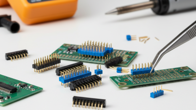
Through-hole headers are mechanically secure and usually easier to solder by hand. They suit prototypes and boards that may see repeated insertion. Surface-mount types save space and avoid drilled holes, but need careful placement and sound solder joints.
Straight headers connect parallel boards or cables; right-angle versions route connections sideways, useful where vertical clearance is limited. Shrouded types guide mating and reduce reversed insertion, though their extra height may not fit. There is no universal best choice.
Compare rated current, contact material, operating temperature, and mating-cycle specifications with the application, not just the purchase price. For a low-profile sensor board, a single-row surface-mount part may fit neatly. For a frequently handled test fixture, through-hole mounting may be more forgiving. I would still verify the drawing and test a sample assembly. Datasheets can leave practical fit questions unresolved.
What Materials and Specifications Should Buyers Evaluate?
What Is the Best Female Header Connector in 2026?
The best female header connector depends on material, environment, and electrical load. A 2024 Grand View Research report valued the global connector market at about USD 82.6 billion in 2023. It also forecasts steady growth through 2030. That growth reflects denser boards and higher reliability demands.
Buyers should inspect the housing first. PBT and nylon suit many general-purpose assemblies, while LCP performs better near heat and tight pitches. Look for a documented UL94 flammability rating and suitable continuous-temperature limits. The contacts usually use copper alloys for conductivity and spring strength. Tin plating works for many indoor applications. Gold plating can reduce contact resistance in demanding or frequently mated connections, but it raises cost. Check the specified mating cycles, not just the plating label.
Electrical specifications need equal attention. Confirm pitch, rated current, voltage, insulation resistance, and PCB thickness. A 2.54-millimeter pitch may simplify hand assembly, while smaller pitches save space but punish alignment errors. IEC 60512 test methods can help compare contact resistance, mechanical strength, and durability. I would not trust a connector based on current rating alone. Temperature rise and wire size can change real performance.
Tips: Request test reports, not marketing claims. Compare contact resistance after cycling. Inspect solder joints under magnification. Allow tolerance for warped boards; perfect alignment rarely survives production. Reports from MarketsandMarkets also identify miniaturization as a major connector trend, although smaller is not automatically better.
What Is the Best Female Header Connector in 2026?
Material and specification comparison for selecting a reliable female header contact.
How to read this chart: Beryllium copper offers the highest typical conductivity and strength, while phosphor bronze provides a balanced combination of spring performance, cost, and corrosion resistance. Brass generally offers good conductivity and economical production but lower spring strength.
Buyer checklist: Evaluate contact plating, rated current, pitch, mating-cycle durability, insulation temperature rating, creepage and clearance, operating temperature, and compatibility with the PCB assembly process. The values shown are representative material references, not guaranteed connector ratings.
How Can You Choose the Right Female Header Connector for Your Application?
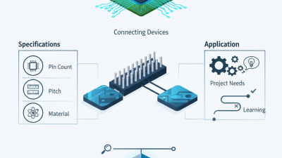
Choosing a female header connector starts with the mating part, not the catalogue photo. Confirm pitch, row count, pin layout, and stack height against the board drawing. A 2.54 mm pitch may suit a roomy prototype, while compact equipment may need a finer pitch and tighter placement control. Check rated current per contact and total connector temperature rise; nearby pins can heat one another. Measure the real operating range, including brief peaks.
Bishop & Associates’ 2024 Connector Industry Forecast reports global connector sales of about $84 billion in 2023, underscoring how broad the market is—not which header fits your design.
For reliability, review contact plating, insertion-cycle rating, insulation temperature, and solder-tail style. Gold plating may help in low-level or frequently mated circuits, but it is not automatically the best choice. Tin can be suitable for less demanding connections. Look for test evidence using IEC 60512 methods, and check whether the stated ratings apply to your exact wire, PCB, and environment.
Small detail. A datasheet may list a current rating under ideal conditions; your enclosed, warm assembly can behave differently.
Prototype the actual stack-up and inspect solder joints before locking the footprint.

 Email
Email WeChat