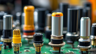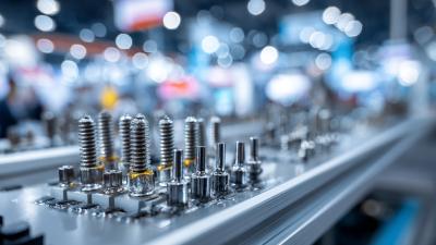


Choosing the right Pin Header can determine whether a compact circuit performs reliably or fails during assembly. In 2026, designers face more options than the familiar single-row and double-row formats. Standard vertical headers, right-angle headers, surface-mount versions, shrouded headers, and high-temperature designs now serve different mechanical and electrical needs. Small parts matter. A few millimeters can affect cable clearance, enclosure fit, and service access.
This introduction outlines the leading Pin Header types and explains where each design performs best. It considers pitch, contact material, mounting method, current capacity, insulation performance, and mating durability. Practical selection also requires attention to soldering temperature, vibration, contamination, and repeated connection cycles. Fit is everything. A header that matches the schematic may still create problems beside a heatsink or moving cable.
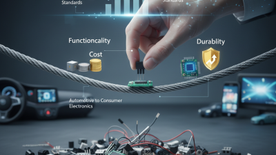
The discussion draws on common PCB assembly practices and established connector evaluation methods. However, connector categories can overlap, and manufacturer specifications are not always presented consistently. A “high-reliability” label needs verification through ratings, test data, and application conditions. No single type wins every design. Engineers should compare drawings, tolerances, plating, and test results before approving a part for production. This guide will also examine emerging priorities for 2026, including automated assembly, reduced board space, stronger retention, and more dependable signal integrity. Some conclusions may change as packaging standards evolve. That uncertainty deserves attention, not concealment.
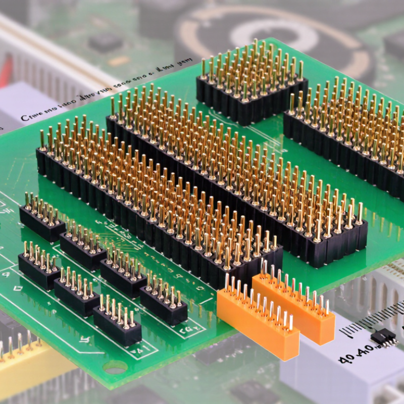
Pin headers are often defined by pitch, the distance between adjacent pin centers. The 2.54 mm pitch remains a practical choice for prototypes, control boards, and hand assembly. It offers visible spacing and easier probing. The 2.00 mm format saves board area without becoming difficult to handle. At 1.27 mm, designers gain higher contact density for compact modules and embedded systems. The 0.80 mm pitch supports very small layouts, but inspection and soldering become less forgiving.
Market context matters. Grand View Research estimated the global connector market at USD 84.26 billion in 2023. Its analysis also identified continuing demand from consumer electronics, automotive systems, and industrial equipment. That growth does not make every smaller pitch superior. A 2026 design still needs to balance current, mating cycles, insulation clearance, and assembly capability. Smaller is useful. Sometimes, smaller is simply harder.
Tips: Confirm the actual pitch with a caliper before ordering. Check pin count, row spacing, tail length, and plating requirements. For 0.80 mm headers, inspect solder joints under magnification. For 2.54 mm parts, reserve enough clearance for probes and repair tools. A footprint copied from an old library may fit badly; review it against the supplier drawing and the applicable IEC connector standard.
What Are the Top Pin Header Types in 2026?
Under IEC 60603-13, through-hole and SMT pin headers must be judged by fit, electrical performance, and production method. Through-hole headers place long pins through the PCB. Their soldered barrels provide strong mechanical anchoring, especially in vibration-heavy equipment. SMT headers sit on surface pads and suit compact boards, automated placement, and high-density layouts. They also reduce drilling steps. However, SMT is not automatically superior.
Grand View Research estimated the global connector market at about US$84 billion in 2023, with continued growth through 2030. IPC’s 2024 electronics industry survey also identified cost pressure and component availability as major manufacturing concerns. These findings matter when selecting headers. Through-hole parts may tolerate repeated mating better, but they can increase board space and assembly effort. SMT parts support faster reflow lines, yet their solder joints may need stronger pad design. In practice, connector height, pin pitch, coplanarity, insulation distance, and contact resistance require careful verification. IEC 60603-13 alignment alone does not prove full product reliability.
Tips: Choose through-hole headers for mechanical loads. Select SMT headers for compact, automated assemblies. Check reflow temperature, mating cycles, and solder-joint strength. A small prototype can reveal problems that a datasheet misses. My own design preference is not fixed; vibration testing may change it.
| Comparison Dimension | Through-Hole Pin Headers | SMT Pin Headers | IEC 60603-13 Design Relevance |
|---|---|---|---|
| Primary PCB attachment | Metal tails pass through plated holes and are soldered on the opposite side. | Contacts are placed on PCB pads and soldered on the component side. | The connector and PCB interface must match the applicable dimensional and performance requirements of the selected standard configuration. |
| Typical pitch options | Common engineering pitches include 2.54 mm, 2.00 mm and 1.27 mm. | Common engineering pitches include 2.54 mm, 2.00 mm and 1.27 mm, subject to package and assembly limits. | Pitch, row spacing, contact layout and mating geometry must be checked against the exact IEC 60603-13 detail specification and product drawing. |
| Mechanical retention | Generally strong because the leads pass through the PCB; retention can be increased with mounting pegs, board locks or solder stakes. | Depends more heavily on solder-joint area, pad design, adhesive support and optional mechanical anchors. | Retention and mechanical robustness should be validated using the applicable connector tests rather than assumed from the mounting method alone. |
| Assembly process | Suitable for wave soldering, selective soldering or hand soldering, depending on materials and component construction. | Designed primarily for solder-paste printing and reflow; some constructions also support selective or hand soldering. | The selected termination must be compatible with the assembly process while maintaining the connector’s specified electrical and mechanical performance. |
| Reflow suitability | Not inherently reflow-compatible; only versions with heat-resistant materials and an approved process profile should enter a reflow line. | Usually the preferred option for automated reflow assembly, provided the component is rated for the specified peak temperature and time above liquidus. | IEC connector compliance does not automatically approve a particular reflow profile; thermal capability must be confirmed separately. |
| Board-side space | Requires drilled plated holes and solder land patterns; the tail length may affect clearance on the opposite side. | Uses surface pads and normally preserves the opposite PCB surface for routing or components. | Creepage, clearance, pad geometry and mating envelope must be evaluated for the intended board design and voltage category. |
| Board repair and replacement | Often easier to mechanically stabilize during rework, but plated-hole removal can require more heat and effort. | Can be quick to replace with suitable equipment, but lifted pads and solder-joint damage are important risks. | After rework, electrical continuity, insulation and mechanical tests should be repeated where required by the qualification plan. |
| Vibration and shock suitability | Often advantageous in mechanically demanding applications because the leads and soldered holes provide additional structural support. | Can perform well when pad design, solder volume, anchoring and board stiffness are properly engineered. | Performance is application-specific and must be demonstrated by the relevant mechanical endurance and environmental tests. |
| Electrical current capability | Common signal-header ratings are frequently in the low-single-digit ampere range per contact, but the actual value depends on contact size, spacing, temperature rise and derating. | Commonly used for signal and low-to-moderate current circuits; actual current depends on contact geometry, solder joints, PCB copper and thermal conditions. | Do not infer a universal current rating from IEC 60603-13; use the specified test method and the exact component rating. |
| Contact resistance | Typically specified by the connector design and measured after defined mating, environmental and mechanical conditioning. | Subject to the same contact-system requirements; the SMT solder joint also contributes to the complete current path. | Use the applicable IEC 60603-13 limit and test conditions for the exact connector family; no single value applies to every header. |
| Insulation performance | Determined by housing material, contact spacing, contamination level, altitude and PCB layout. | Determined by the same connector factors, plus surface-pad spacing and solder-mask design. | Working voltage, dielectric withstand and insulation resistance must be taken from the applicable specification and end-use environment. |
| Best-fit applications | Board-to-board interfaces, test fixtures, control boards and assemblies where mechanical strength is a priority. | High-volume automated production, compact boards and assemblies designed around surface-mount placement. | Select the termination style based on the complete mechanical, electrical, environmental and manufacturing qualification plan. |
| Overall 2026 selection guidance | Choose through-hole when board retention, repeated handling or harsh mechanical conditions outweigh assembly density. | Choose SMT when automated placement, reflow throughput and preservation of the PCB’s opposite-side routing area are primary objectives. | IEC 60603-13 alignment requires verification of the exact connector geometry, ratings, materials, test results and declared termination method; mounting style alone is not proof of compliance. |
In 2026, pin header selection depends more on PCB geometry than popularity. Straight headers rise perpendicular to the board. They suit cables, sockets, and test points above the PCB. A 2.54 mm pitch is common, but smaller pitches save space. Check housing height before placing nearby components. Measure twice.
The term “vertical header” can overlap with “straight header” in supplier catalogs. Both usually place pins upright from the board surface. This naming difference deserves attention during procurement.
Right-angle headers turn the pins parallel to the PCB. They work well along board edges, where cables must exit sideways. They can also reduce enclosure height. However, their horizontal reach needs a clear mechanical path. A nearby heatsink or wall may block insertion.
During layout reviews, I check the connector’s keepout zone, pin numbering, and cable bend radius. I also confirm whether the solder tails fit the selected hole diameter. Through-hole headers provide strong mechanical support for repeated mating. Surface-mount versions can simplify assembly but need careful pad and support design. Plated contacts matter for corrosion resistance and stable electrical contact. Do not ignore vibration. A perfectly routed header can still fail when the cable pulls against it. I once approved a compact right-angle layout too quickly; the housing collided with the enclosure. That mistake changed the drawing, not the physics. Prototype the actual board, cable, and enclosure together before release.
In 2.54-mm IDC systems, shrouded and ejector headers remain practical choices. Their value is not simply pin density. It is controlled mating. A shrouded header surrounds the pins and supports polarization through a keyed housing. This reduces reversed insertion during service work. It also protects contacts from accidental side impacts.
Ejector headers add levers for cable removal. That detail matters in dense control cabinets, where fingers cannot grip a short ribbon cable. The levers apply balanced force across the connector. They can also improve removal consistency after repeated maintenance cycles. IEC 60603-13 provides a useful reference for rectangular connectors and IDC-related interfaces. Designers should still verify the exact cable, insulation displacement geometry, and current rating.
Market context supports careful selection. Grand View Research valued the global connectors market at about 84.8 billion dollars in 2023. Its report expects roughly 6.3% compound annual growth from 2024 to 2030. That expansion increases pressure for compact, serviceable interconnects. However, market growth does not guarantee field reliability.
A small admission: ejector levers can become clearance problems near enclosure walls. Shrouded headers may also complicate visual inspection.
I would prototype both options with the actual ribbon cable, latch force, and access angle. The best header is often decided by maintenance space, not the catalog drawing.
What Are the Top Pin Header Types in 2026?
For most signal and low-power boards, pin headers rated around 1–3 A cover practical connection needs. The exact rating depends on pitch, contact plating, pin length, and temperature. A single-row header suits compact sensor boards and simple wire links. A double-row version saves board space when many signals share one connector. Right-angle headers work well beside an enclosure wall. Shrouded headers add keying and reduce accidental misalignment.
Current ratings need careful reading. A 2.54 mm header may carry 3 A under limited conditions, but heat rises when several adjacent pins carry current. Smaller pitches often need lower working currents. Check whether the rating applies per pin or across a loaded group. This detail is easy to miss.
UL 94 V-0 material is a useful safety indicator because the plastic can self-extinguish after ignition under the test method. It does not prove that the connector handles 3 A safely. Designers still need to review contact resistance, insulation spacing, operating temperature, and derating data. In a prototype review, I once focused too much on the flame rating and overlooked cable-side heating. That was a poor decision. Measure real temperature during peak load. Also inspect solder joints, especially on tall headers that receive repeated plugging force. A low-cost header may pass initial testing yet feel loose after many cycles. Choose the type that matches current, space, alignment, and actual mechanical use.
Representative typical current ratings for widely used pin header types. Actual limits depend on pitch, contact size, temperature rise, plating, and PCB design.
Common for board-to-board and wire-to-board connections, especially at 2.54 mm pitch.
Useful when cable access is needed from the side of the PCB.
Polarization and keying help reduce connector misalignment during assembly.
For designs targeting typical 1–3 A operation, select a header with a UL 94 V-0-rated housing material such as suitable flame-retardant PBT or PA66, then verify the individual component’s electrical and thermal specifications.